I have been watching TRS80 model 1 and model 3 computers come and go on ebay for a long time, but this one caught my eye. Even though it was not working, it was clearly a good candidate for restoration, because;
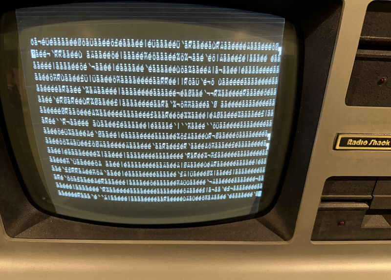
- Even though the screen was garbled, the CRT and video section were clearly working with a steady strong image.
- It was a local 240VAC model; not a 110VAC import
- It was fully optioned with 48K RAM, RS232 and floppy drives
- Keyboard was complete; no missing key tops.
- Cosmetically complete and well presented
I also know the TRS80 circuit inside out, and having recently restored a more complex Z80 based computer (the Compustar), I am confident that I can get this one working as well. So the journey begins….
First impressions
I received the computer well packed; thanks Hans! He had taken extra care to pack it extremely well. This is a real bonus, as some sellers don’t bother.
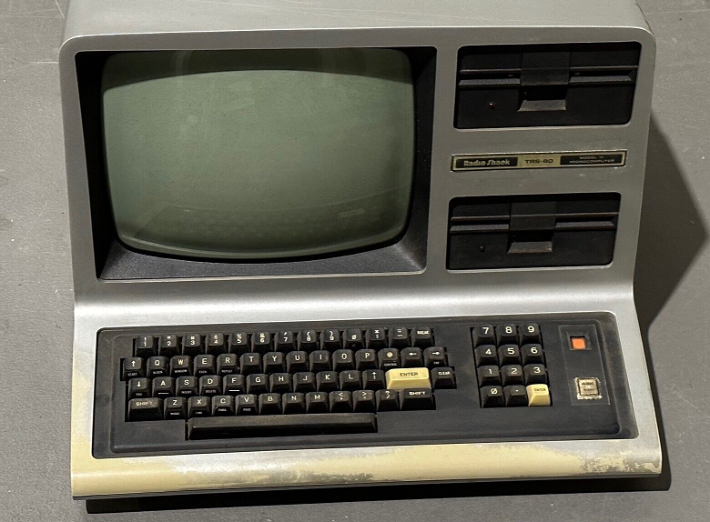
The only significant cosmetic problem is the severely worn silver paint at the front of the keyboard. This must have been a real workhorse computer in an office; probably for word processing, since there are WP shortcut stickers on some keys. But this is not a problem. The case and keyboard are in exceptionally good condition; all the keys appear to work. And after a simple clean with nothing more than a damp cloth, it looks almost new!
First power on, and the screen appeared exactly as advertised. Interestingly though, one disk drive fires up and does the same when the reset key is pressed. Hopefully this indicates that the CPU is running and the FDC is operational; is it just the video section which cannot be accessed by the CPU which causes the garbage? So that will be the first place I will look.
Phssssss……. Smoke!
So while it was turned on, I got out the multimeter and checked all the voltages. These were all good; with no ripple.
There are two identical power supplies; one for the CPU board and RS232, and one for the FDC and floppy drives. Since I would need to look at the CPU board first, I decided to disconnect the floppy power supply and disconnect the FDC and RS232 from the CPU board.
Upon the next power up, I was surprised when I turned it on, because it was so silent. Of course! You expect some noise turning on a computer these days because of fans and disks, but this was totally silent. Anyway after a few minutes, one of the power supplies emitted some smoke. It didn’t appear to affect anything else, the screen continued to display the same image. But to be safe I turned it off!
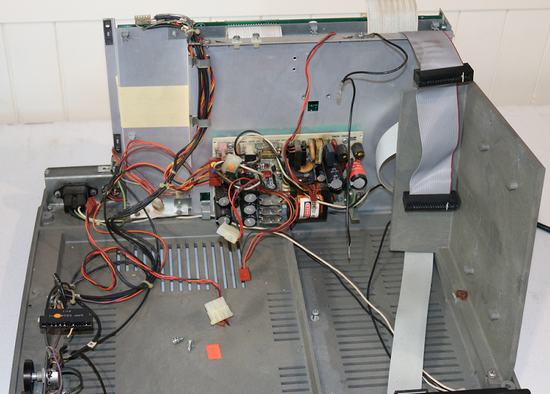
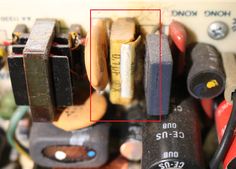
Unfortunately, the power supply which blew smoke was the one for the CPU, and you have to disassemble the entire floppy drive cage to access it. So I now have the chassis entirely stripped down without the floppy drive cage. Removal of the power supply revealed that the culprit was a simple 100nf capacitor across the primary rectifier. This explains why it didn’t affect anything else (fortunately). There is also another similar 10nf with plastic packaging showing cracking. So I will replace both of these in both power supplies.
CPU diagnostics
iWith the faulty capacitors replaced and the power supply repaired I was confident about continuing with examinining the CPU.
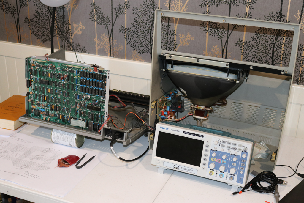
On the bench I placed the main chassis backwards with the main PCB facing me. Then the upper case with the CRT could be attached and placed to the side so I would be able to see the display. If you are doing this, be sure to keep the thick earth lead on the CRT circuit board attached to the earth on the main chassis, otherwise the turn on current can damage the main PCB.
First, I attached the oscilloscope to the M1 pin of the Z80 (pin 27) and triggered the scope on this. Most of the time, the consistency of the waveform indicated that the processor was halted, executing NOP instructions. But occassionally, after pressing the reset button, the CPU would start executing something; although this appeared to be quite random.
But this activity allowed me to examine the data and address buses, and to examine the address decoding logic. I replaced the Z80 CPU, just in case, but this did not make any difference.
Occasionally, after executing some random code, the CPU would halt. Examination of the buses and address decoding logic did not show any problems, so I started looking more closely at the RAM.
Signs of life!
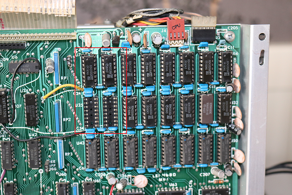
Since the unit is fully populated with 48k RAM, there are 24 chips to choose from, but obviously the fault is probably going to be in the lowest 16k bank. So I tried bits 0 and 1 first; swapping these with the same chips in bank 1; but this did not make any difference.
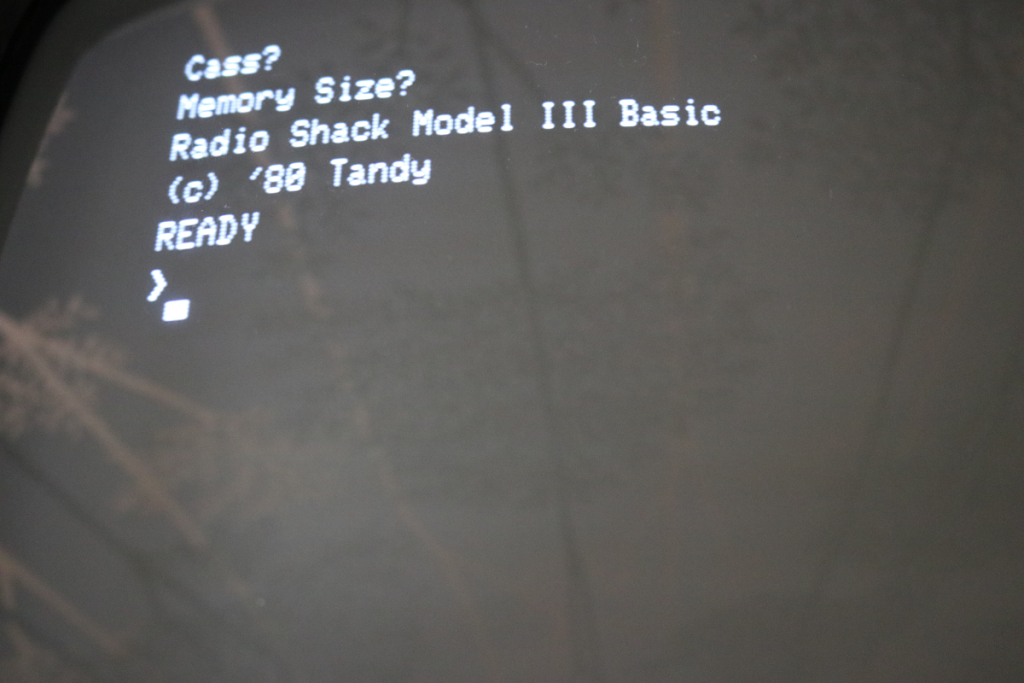
So next I tried swapping bits 6 and 7. Lucky strike! When I powered up the computer, the screen displayed the Familiar “Cass?” prompt, and pressing the enter key displayed the “Memory size” and BASIC prompts!
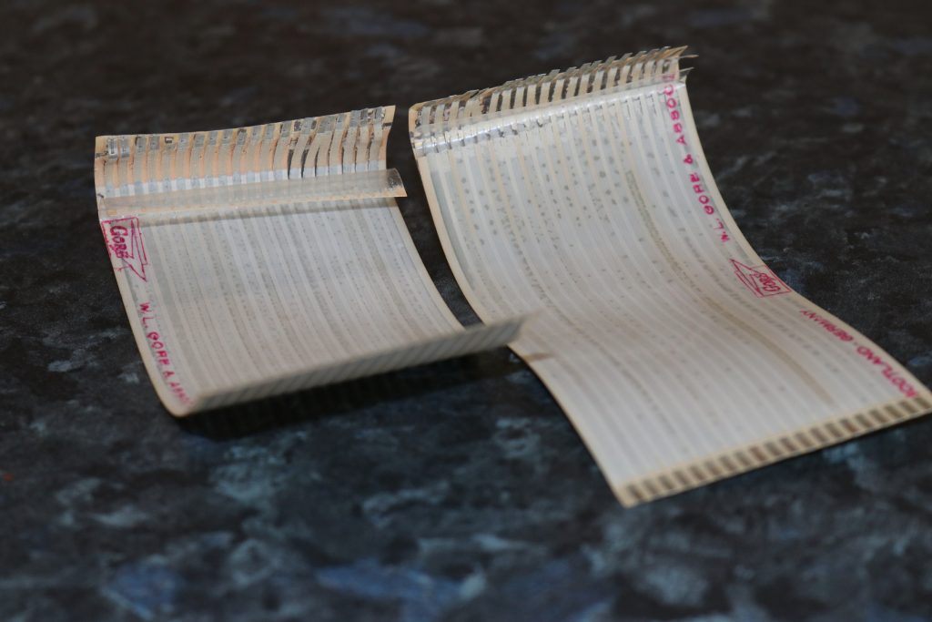
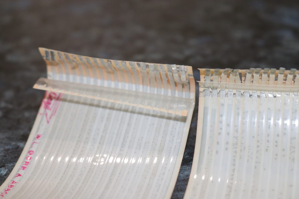
So in the end, the problem causing the garbled display was simply repaired by replacing one 4116 DRAM chip. But at this stage, the RS232 and disk controllers had been left disconnected from the main CPU board and needed to be tested. But first, the ribbon cables which interconnect these boards were in poor condition and needed to be replaced.
I posted these photos on the Australian Computer Museum Society FB group page, and very quickly found that I could purchase brand new riboon cables from Ian Mavric at trs-80.com. Thanks Ian!
Testing the cassette input
While I waited for the replacement ribbon cables and RAM chip, I tested the cassette interface. There is so much TRS80 software out there, and a lot of it exists as “CAS” files.
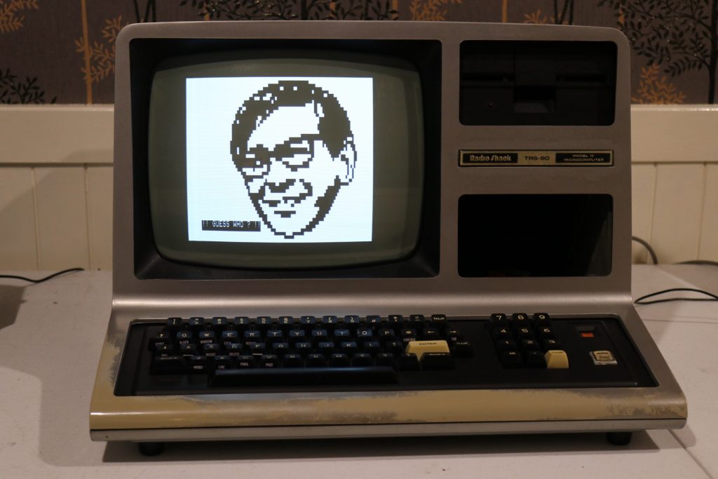
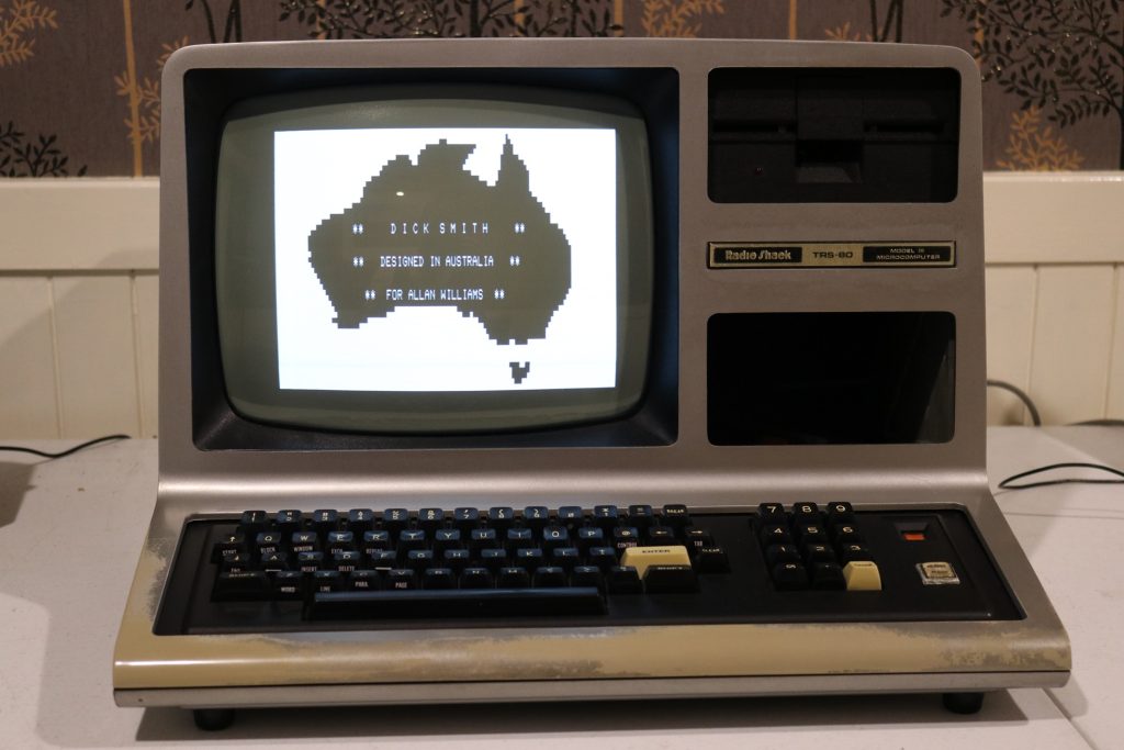
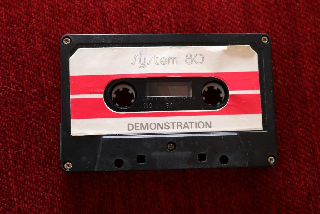
To test it, I used one which I was familiar with from my first encounter with these computers. That computer was a “Dick Smith System 80”, and like most other people, the first program I ran was from the demonstration cassette which was supplied with it.
I didn’t use the actual cassette. Instead I used the “playcas.exe” program which plays CAF files on your PC. I simply connected the headphone output of the PC to the cassette input of the TRS80 and set the volume to maximum, and I had no problem loading the “DSLOGO.CAS” program in this way.
This also revealed some of the differences between a Model III and the Model I (that this demo program was written for). First of all, I had to set the cassette speed to low (500 baud) by executing “POKE 16913,0” in BASIC before running CLOAD. And after the program was loaded, I needed to edit it and change a couple of lines from “POKE S,255” to “POKE S,191”. These are the lines which set the two pages to solid white. The Model 1 uses codes 128-255 for the block graphics and repeats these codes in ranges 128-191 and 192-255. The Model III uses the second range for international character sets.
Floppy disk drives
The computer had 2 single sided, double density disk drives. The brand name is “Texas Peripherals” which was apparently an early venture by Tandy and Datapoint to produce disk drives. What is particularly unique about these drives is that the servo PCB is mounted underneath the drive instead of at the rear, like most other brands. And it looks like this was a special arrangement for the Model III, otherwise the drives simply would not fit in the drive bays which are too shallow.
Also, what is unique about these drives is that the usual DIL socket where the DIP switches are on other brands is empty. Instead, the drive selection is achieved by connector pins being absent in the ribbon cable edge connector, so that the ribbon cable has fixed positions for drives “0” and “1”.
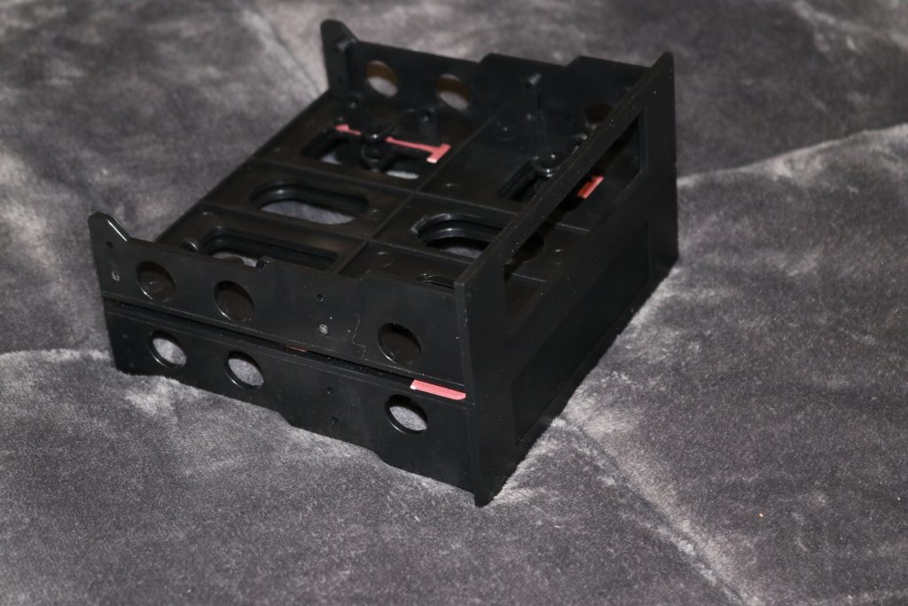
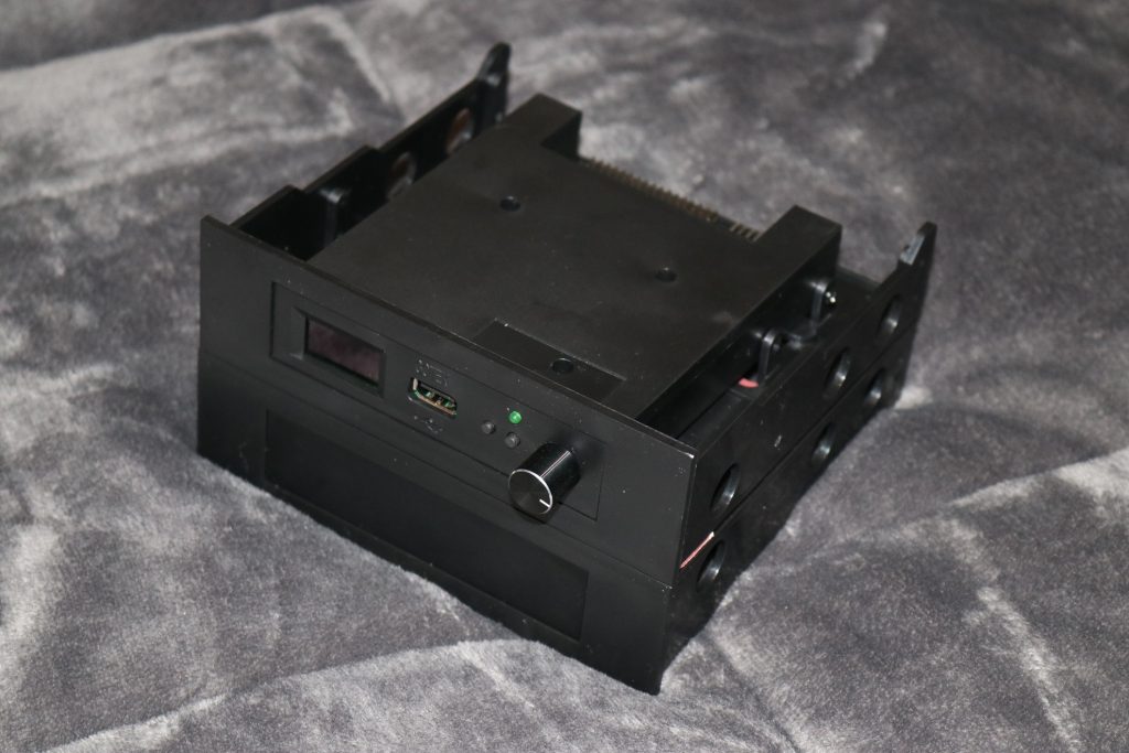
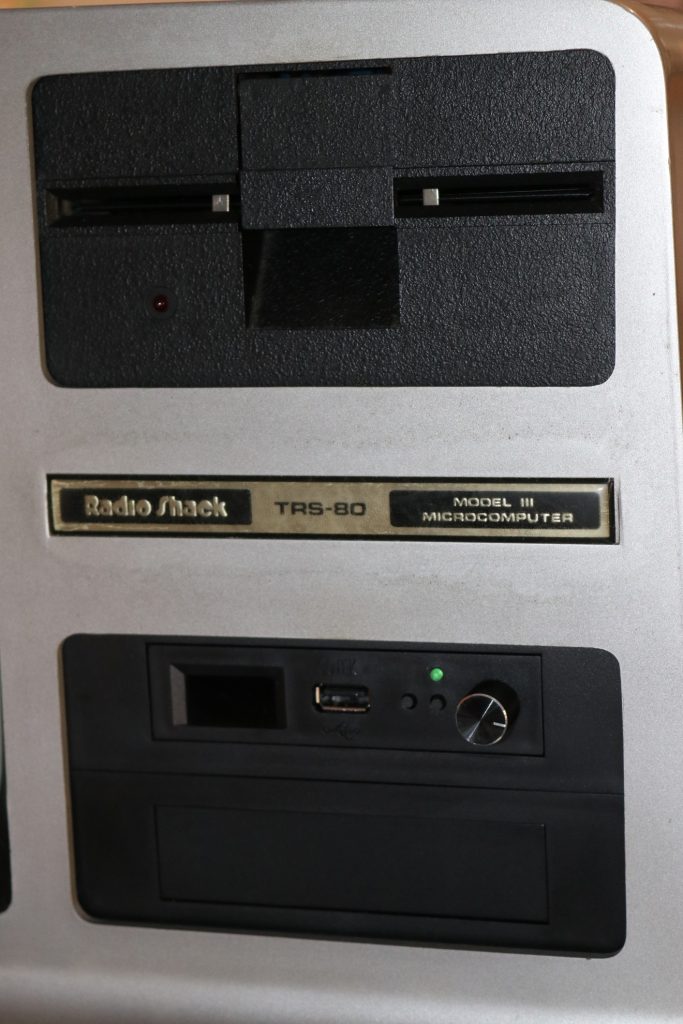
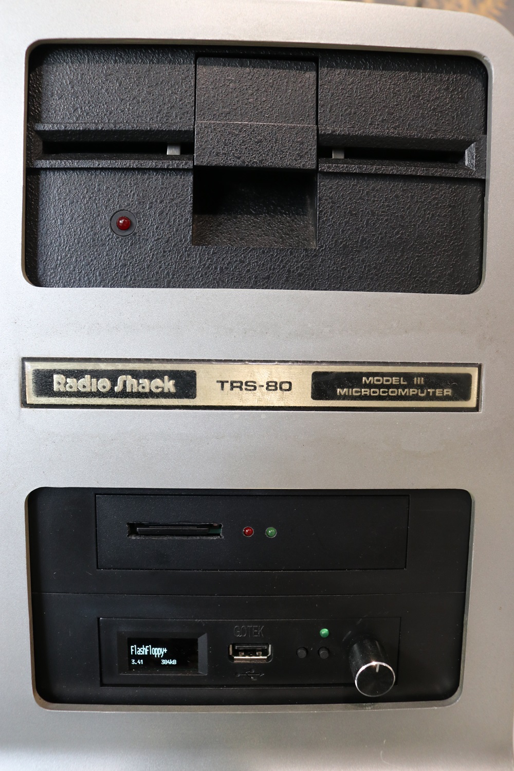
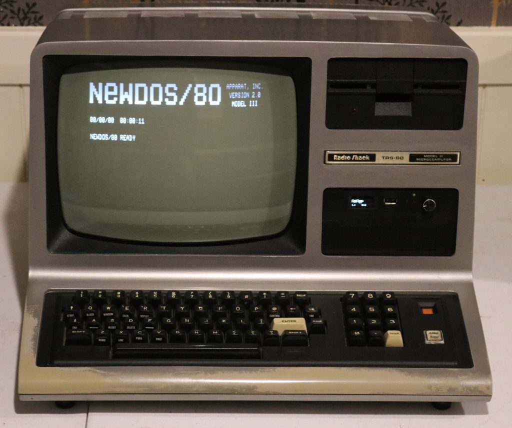
Of the two original drives, one had a faulty door. So I have left the working drive in position “1” and replaced drive “0” with a Gotek unit running “flashfloppy”. This has been accommodated in the original drive bay by joining two blank 3.5/5.25 floppy disk adaptors together to make a full height piece and installing the Gotek unit in the upper half.
This arrangement has worked well, and I have not found any fault in the floppy controller; even with the external interface. The arrnage ment of the Gotek unit also provides space in the lower half for installation of a FreHD unit as a future option.
Serial interface
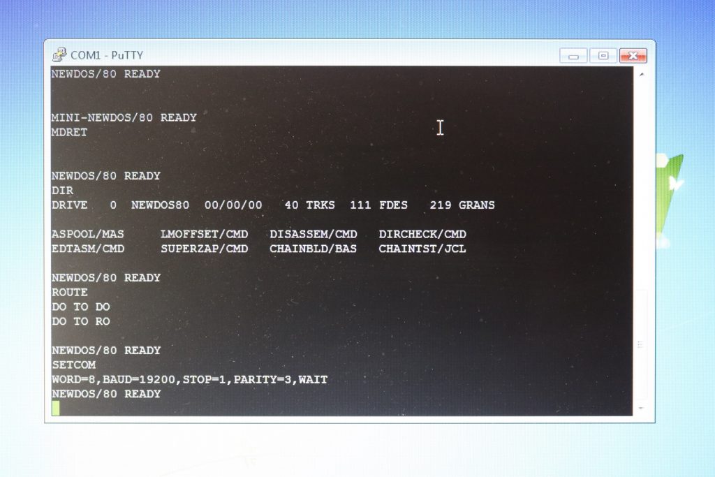
With everything else working in the computer, the only remaining untested part was the RS232 serial interface. To test this, I attached it via a serial break-out unit on the cable into my laptop running “Putty” terminal emulator and used SETCOM and ROUTE commands to redirect I/O to the terminal. The DTR and RTS signals were active, but these was nothing on the TXD signal from the Model III. So this would require further diagnosis.
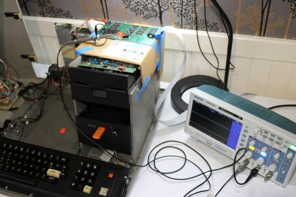
Unfortunately, the seral board is hidden behind the main board and it’s mount plate. So to examine the board, I had to lift it from this position and place it onto of the floppy bay. There is sufficient length in the cable with attaches it to the main board to do this so that the PCB could be simply taped to the top of the floppy bay in a secure manner for testing with the oscilloscope.
Testing quickly revealed that there was no TX/RX clock signal from the programmable baud rate generator (BRG) to the UART. This clock is derived from the 5MHz clock on the main board. This passes through a 7404 TTL inverter pair to the BRG . In my experience with these systems, I have sometimes found that the clock can appear weak on the the oscilloscope, and it may be insufficient to drive the old CMOS chips like the BRG, so I replaced it with a 74HC04 which gives a strong square clock. Unfortunately this did not solve the problem, so the BRG would need to be replaced next.
So I ordered a AY-5-8116 to replace the BR19411 BRG chip. These are identical. When it arrived and I replaced it on the board, the UART clock signal was restored and testing revealed no other problems, so I was able to finally complete and close up the entire Model III case!
FreHD adaptor installation
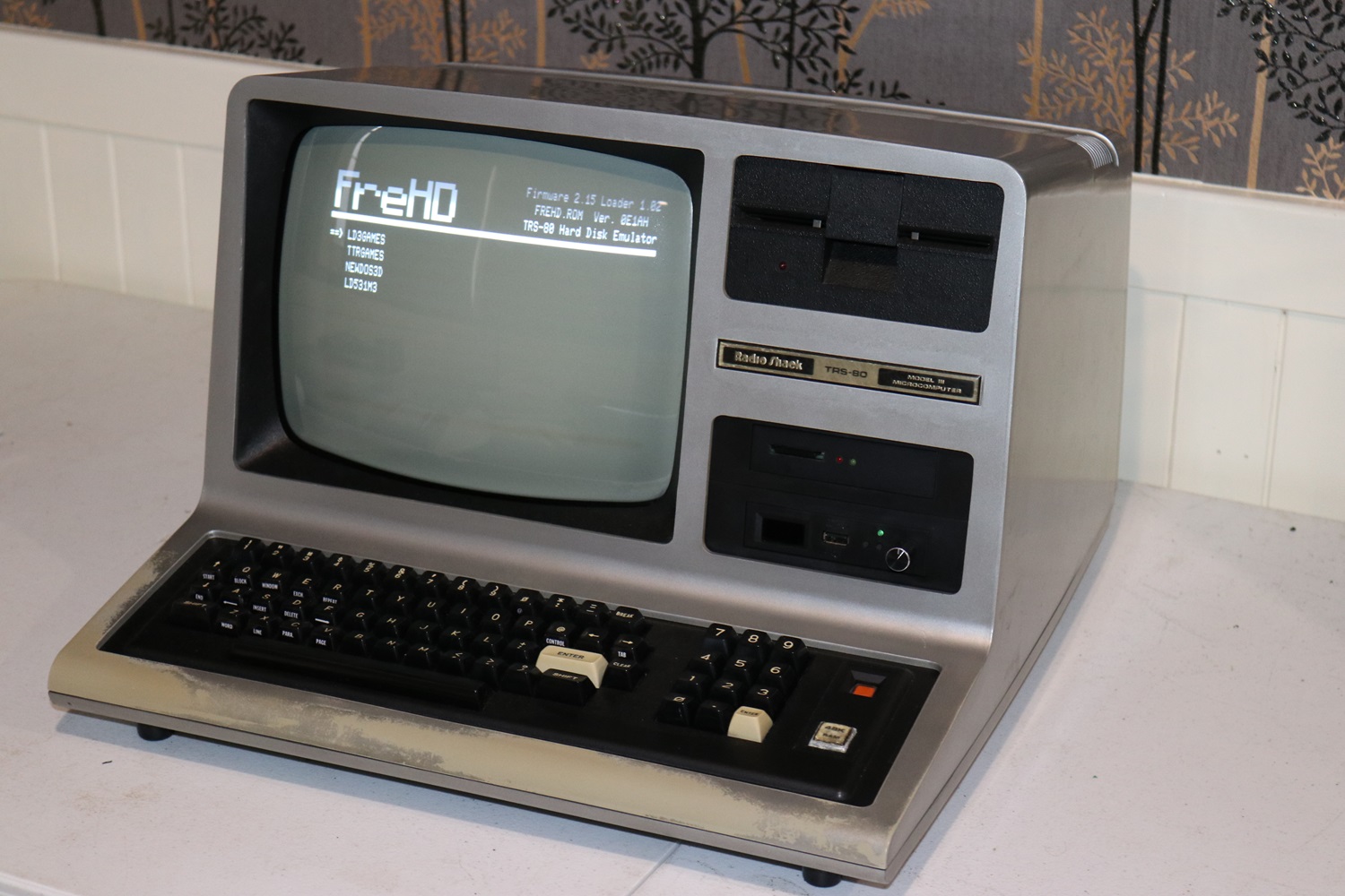
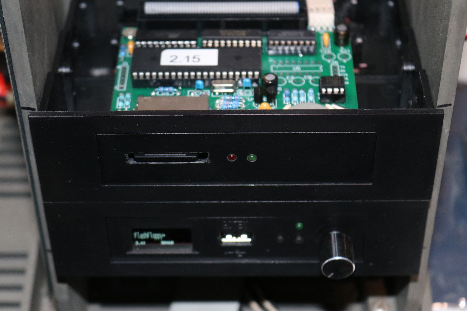
I decided to press ahead and install a FreHD unit as well. This has been installed internally using the spare space adjacent to the Gotek drive with the 50way ribbon cable routed inside the machine. This makes for a neat installation, and having a “hard disk” makes the machine far more useful. Thanks once again to Ian from trs-80.com who supplies these units.
I replaced the two LEDs on the supplied FreHD circuit board with small forward facing LEDs and then mounted the unit in the spare 3.5″ space and made a slot in the face for the SD card using a rotary tool.
